RFID authentication
Scans an RFID card or tag using an RC522 module before allowing PIN entry.
Arduino / Robotics
An Arduino access-control prototype combining RFID authentication, keypad PIN entry, servo locking, buzzer feedback, and LED matrix status display.
I built this to move beyond basic Arduino component tutorials and combine several starter-kit modules into one working physical interaction demo.
Project overview
I built a working RFID security console using an Elegoo Uno R3 starter kit. The project combines multiple modules into one interactive system: an RC522 RFID reader, 4x4 keypad, SG90 servo, active buzzer, and MAX7219 LED matrix.
Instead of only testing individual components, I wired them together into a small access-control prototype where the correct RFID tag enables PIN entry, the keypad checks the passcode, and the servo physically unlocks a cardboard latch mechanism.
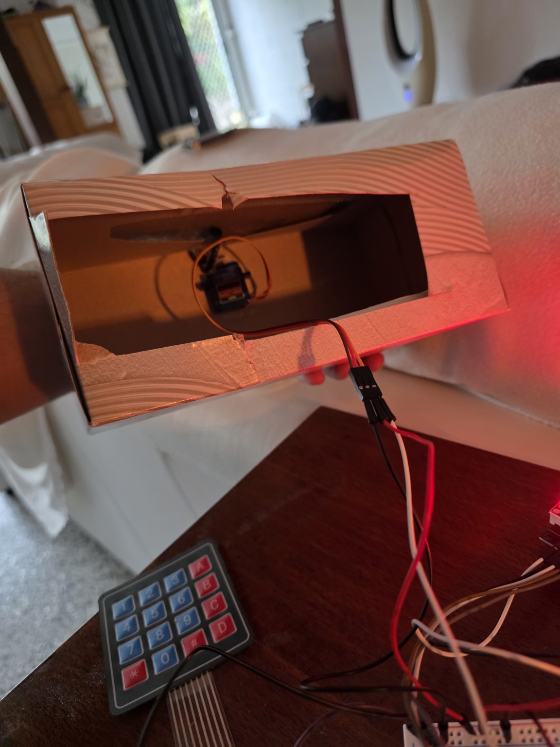
The enclosure was intentionally built without a 3D printer, using a cardboard box and a simple servo-blocking latch. This kept the focus on electronics, wiring, state logic, debugging, and rapid prototyping. The result is a functional proof of concept that demonstrates how sensors, input devices, visual feedback, and mechanical movement can work together in one embedded system.
Demo flow
The interaction is intentionally simple: scan the accepted RFID tag, enter the PIN on the keypad, then let the servo rotate out of the way so the cardboard latch can open. Wrong PIN attempts increase a counter, and repeated failures trigger an alarm state with buzzer feedback.
How it works
The system waits for an accepted RFID tag before allowing PIN entry. From there, the Arduino decides whether to unlock the servo latch, count a failed attempt, trigger alarm feedback, or return to the locked state.
The RC522 module reads the card UID and sends it to the Arduino for checking.
If the UID matches the accepted tag, the system moves from locked state into PIN entry.
The 4x4 keypad handles passcode input, clear, submit, and cancel controls.
A correct PIN continues the unlock flow. An incorrect PIN increases the failed-attempt counter.
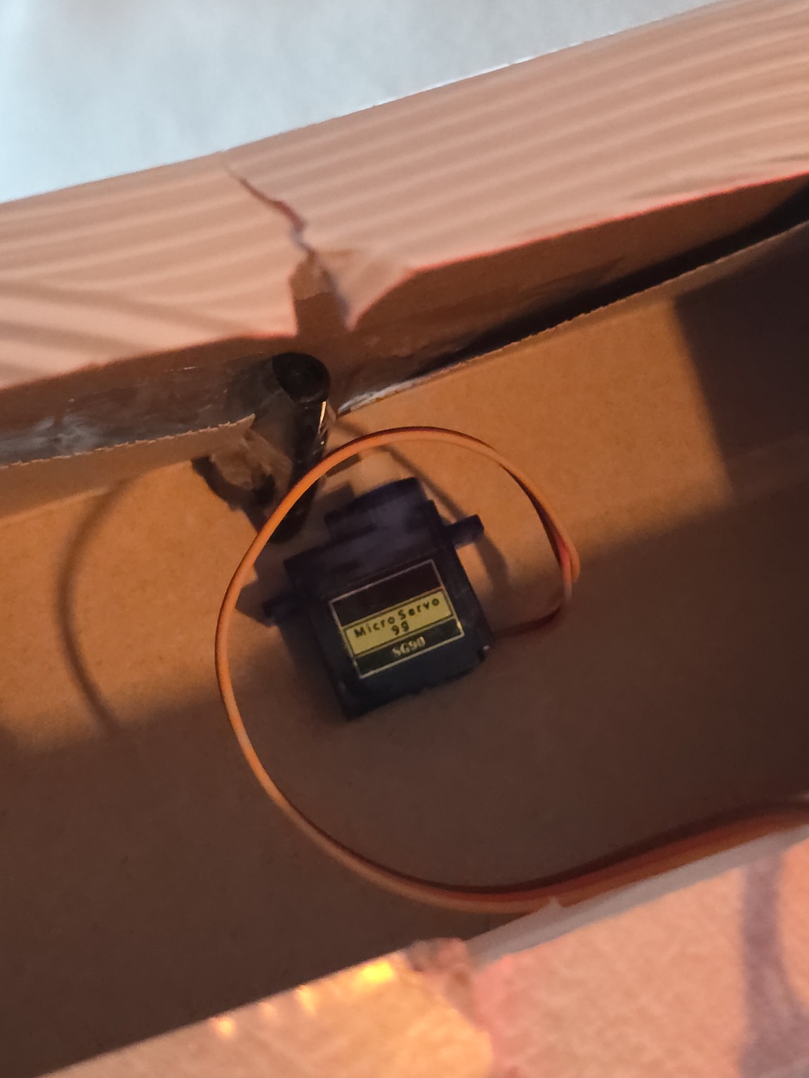
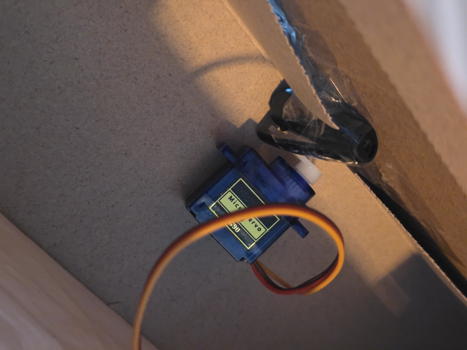
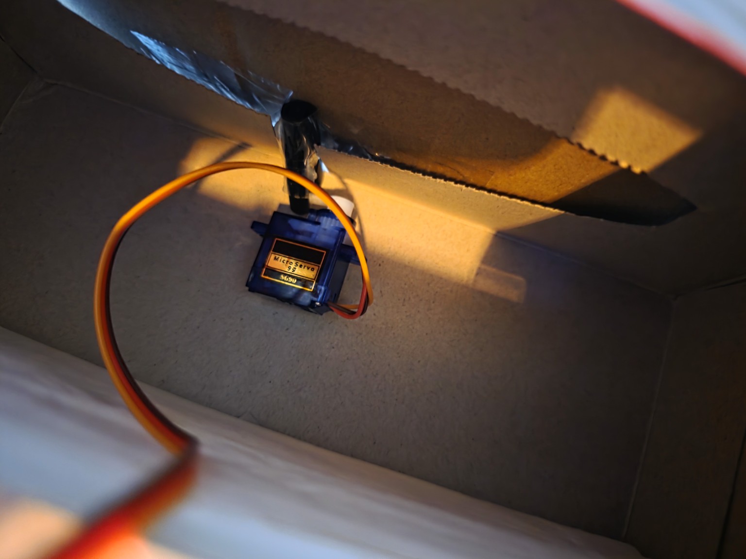
The SG90 servo rotates away from the cardboard latch so the box can be opened.
The LED matrix and buzzer communicate success, error, status, or alarm behaviour.
Repeated failed PIN attempts trigger alarm mode instead of continuing to accept input.
After a delay, the servo returns to the blocked position and the system waits for RFID again.
Features
Scans an RFID card or tag using an RC522 module before allowing PIN entry.
Uses a 4x4 membrane keypad for passcode input, clear, submit, and cancel controls.
Uses an SG90 servo to block or release a cardboard latch instead of trying to pull the box open.
Uses a MAX7219 8x8 LED matrix to show lock, unlock, error, and status icons.
Uses an active buzzer for success, error, and alarm feedback.
Includes wrong-attempt tracking and alarm mode after repeated incorrect PIN attempts.
Hardware build
I used cardboard because the first version did not need a 3D-printed enclosure to be useful. The aim was to prove the electronics, the logic, and the physical blocking mechanism before spending time on a polished case.
The servo does not pull the lid open. It works as a rotating blocker: in the locked state, it prevents the cardboard latch from moving; in the unlocked state, it rotates away so the latch can be released. That made the mechanical side simpler and more reliable for a starter-kit prototype.
Technical details
| Board | Elegoo Uno R3 / Arduino Uno-compatible board |
|---|---|
| RFID | RC522 RFID module |
| Input | 4x4 membrane keypad |
| Output | MAX7219 8x8 LED matrix, active buzzer |
| Actuator | SG90 micro servo |
| Enclosure | Cardboard prototype box |
| Core logic | RFID scan → PIN entry → servo unlock → timed relock / alarm mode |
| Language | Arduino C/C++ |
What I learned
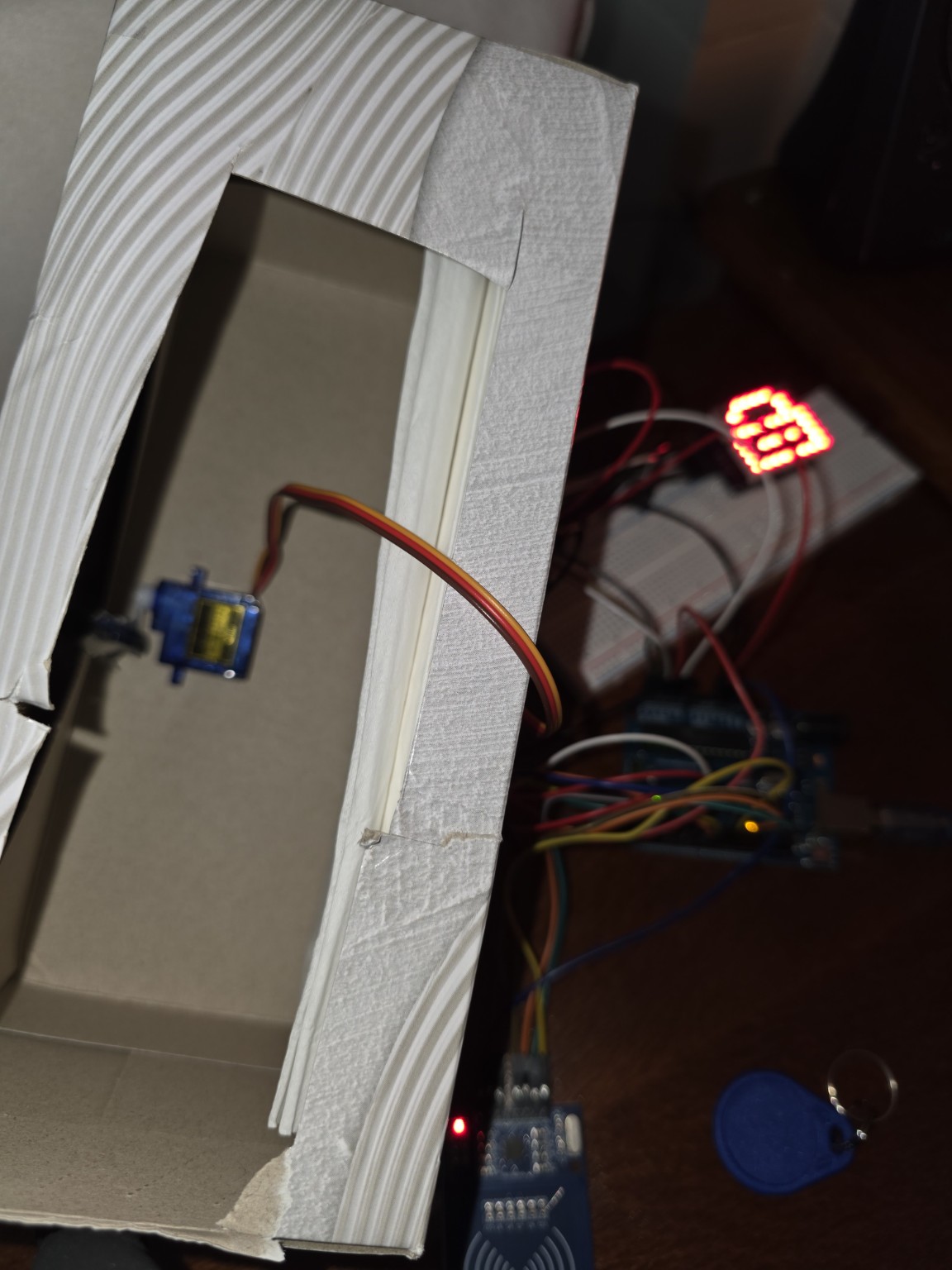
The biggest learning curve was planning the full system instead of treating each module as an isolated tutorial. Once the RFID reader, keypad, servo, buzzer, and LED matrix were all connected, pin usage, shared ground, power behaviour, and state logic became much more important.
Build gallery
The gallery shows the latch position, wider electronics layout, and the physical movement of the mechanism.